
A good setup keeps the unit under test (UUT) connection separate from the instruments, switching, signal conditioning and software that serve more than one UUT. The connectors that belong to a single UUT sit in a smaller adapter, and each function maps to a named signal. Open modular standards can cut down on duplicate fixtures and keep some of the impact of a change contained. They don’t get rid of adapters, they don’t make every signal type a good fit for sharing, and they don’t remove signal path effects, which still have to be budgeted.
Many aerospace and defence automated test equipment (ATE) systems grow one programme at a time. Each new unit under test (UUT) can bring its own fixture, harness and test programme. Years later, an instrument may reach end of life and trigger checks across the connected chain. A reusable signal interface for ATE systems separates the UUT connection that changes from the instruments, switching, and software intended to serve more than one configuration.
What is a reusable signal interface in an ATE system?
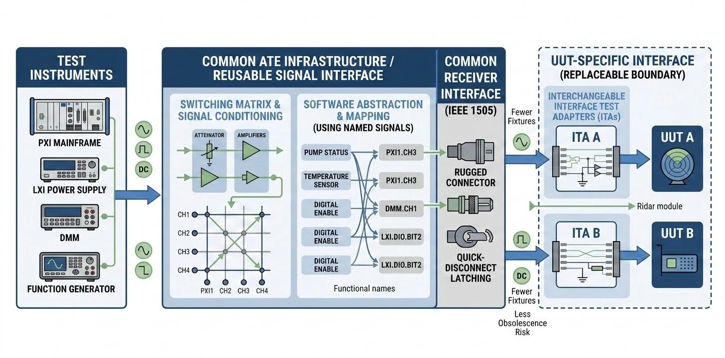
A reusable signal interface is a defined layer between test instruments and the UUT that routes, conditions, and names signals consistently. It allows shared instruments and software to serve different UUTs through a UUT-specific connection and an explicit mapping. A switching matrix routes selected instrument channels to the named functions in that inventory.
A signal inventory (ie. named signals) records each function, its type, range, bandwidth, direction, associated UUT, and special requirements. The signal name layer lets a test step call a function such as “pump status” rather than a fixed card or channel number; the mapping assigns that function to the instrument channel and adapter pin for each UUT.
An interface test adapter (ITA), often used with a receiver, forms the mechanical and electrical boundary between the test system and one UUT. The common receiver stays with the ATE, while a smaller adapter carries the UUT connector, pin map, and mechanical fit. UUT-specific details sit in that replaceable boundary.
Why do fixtures multiply, and why does obsolescence risk follow?
Fixtures multiply when each programme wires instruments directly to its own UUT, leaving the harness, route and test software tied to that arrangement. Obsolescence risk follows when those elements also depend on a particular instrument, driver or support path.
In a tightly coupled setup, instrument selection, pinouts, signal names, test limits and calibration records can all point to one device model. Moving a signal or replacing a module can then affect the harness and configuration together. A new UUT adds exceptions instead of a controlled adapter and mapping.
Take a pressure transducer that appears on two UUTs. On a directly wired system, each UUT gets its own harness, its own channel and its own copy of the test step that reads it. If the module behind that channel reaches end of life, both UUTs need new wiring, new limits and a repeat verification. With a named signal and a mapping, the same replacement becomes a change to one mapping entry per UUT, plus the verification that goes with it.
Diminishing manufacturing sources and material shortages (DMSMS) describe risks created when manufacturers, materials or software support become unavailable. The Defense Standardization Program Office’s public DMSMS guidance calls for proactive management to reduce effects on readiness, schedule and cost.
A programme may need its instruments, boards and software to last longer than their individual support windows. When functions, wiring and code have no stable mapping between them, a single end-of-life notice can affect several UUT configurations.
Where those boundaries sit decides how far a change travels: when a module or driver is replaced, the mapping shows which signals, adapters and test functions it touches.
What does a reusable signal interface for ATE systems include?
A reusable signal interface has five layers from instrumentation to the UUT connection, each with a documented boundary. The table shows what can remain common and what will usually vary by UUT.
Layer # - Description | What it does | What should stay stable | What changes per UUT |
|---|---|---|---|
#1 - Instruments and input/output modules | Source or measure signals and provide digital control. | Functions, module limits, calibration records and channel naming rules. | Channel assignment, range and module choice where requirements differ. |
#2 - Switching and routing | Connect selected instrument channels to named signal functions. | Route names, safe states, control logic and state records. | The route map and unused contacts for each UUT. |
#3 - Signal conditioning | Scale, isolate, filter or excite signals for the measurement. | Configuration records, calibration method and documented limits. | The settings and conditioning modules needed by each sensor or signal group. |
#4 - Connection interface and adapter | Connect the system to the UUT mechanically and electrically. | Receiver boundary, common pin functions and interface drawings. | UUT-specific connector, pin map, fit and special wiring. |
#5 - Software abstraction | Map functional names to drivers, channels and calibration data. | Signal names, application interface, data fields and change records. | The UUT mapping, test limits and any unique sequence. |
The software can address named functions rather than fixed card locations. A mapping assigns each function to a channel, range, calibration record, and adapter pin; a new UUT may need a new adapter and mapping even when the common instruments remain.
The VTEST EMX Series PXIe mainframes with software-interchangeable I/O boards offer one example of a shared instrument layer for configurations that use different UUT adapters.
Also, VTEST's Universal Interface and Signal Conditioning Interconnect Solution is another type of reusable adapter that gives direct access to module channels and manual routing, signal conditioning, as well as connection interface options all at the same time.

Universal Interface and Signal Conditioning Board from VTEST is a modular platform with reusable signal interfaces
How do open standards reduce obsolescence risk?
Open standards set rules at different system boundaries. PXI and LXI define instrument form and communication, while driver and test description standards give software a consistent way to address instruments and describe tests.
The PXI standard defines a modular, chassis-based instrument architecture with mechanical, electrical, and software requirements. Its shared backplane provides communication, timing, and triggering; PXI Express (PXIe) uses PCI Express for higher data bandwidth. Teams choose PXI for coordinated modules in one chassis and PXIe when the system needs more backplane bandwidth; see the PXI Systems Alliance overview.
The LXI standard defines Ethernet-based communication and required core functions for networked instruments, rather than a shared card chassis. Teams typically choose LXI when instruments need flexible placement across a bench or rack; optional extensions add functions such as a browser interface, as described in the LXI core features.
Interchangeable Virtual Instrument (IVI) driver classes give a test program common calls instead of code tied to one instrument model. When a replacement supports the same class and required functions, this can reduce driver changes; the IVI driver standards describe the architecture and APIs.
IEEE 1671 defines the Automatic Test Markup Language (ATML) family for exchanging test system and test information in Extensible Markup Language (XML); the IEEE 1671 abstract sets out that scope.
IEEE 1505 defines a mechanical and electrical quick disconnect between a test system receiver and a UUT fixture panel, as described in the IEEE 1505 abstract.

IEEE-1505 defines rugged mass interconnect solutions
Each standard covers one boundary, and none of them replaces the signal inventory, which still decides which modules, routes, and test functions each UUT needs. Mass interconnect systems, such as those provided by Virginia Panel Corporation (VPC), offer standardized modular receiver and Interface Test Adapter (ITA) solutions that enable rapid, repeatable connections between complex ATE switching infrastructure and diverse UUT configurations.
What can a reusable signal interface not do?
A reusable interface defines what the test system can share; the UUT still sets the physical connection and signal requirements.
Adapters and dedicated fixtures remain necessary for unique connectors, mechanical fit, or environmental chamber constraints, shifting UUT-specific work into a smaller boundary rather than eliminating it.
Switch resistance and capacitance can alter routed signals, while thermal offsets, bandwidth limits, crosstalk, and measurement uncertainty can also impact results depending on the setup.
Wideband radio frequency (RF) signals, like those in radar testing, may require dedicated paths (e.g., VTEST’s RF and microwave switching systems).
Hardware standards do not maintain software or calibration, requiring separate sustainment planning for aging drivers, operating systems, and calibration procedures.
Seemingly equivalent replacement components can still differ in accuracy, bandwidth, timing, or behavior.
Upfront effort is required for inventory, naming rules, and mapping before connecting the first UUT, with reuse benefits returning when subsequent UUTs share signal functions.
Generalized architectures can complicate field testing, and shared systems introduce scheduling dependencies across programs.
How do you plan a reusable signal interface for ATE systems?
Start with the UUTs in scope, list every signal, group signals by type and requirement, then define the layers and boundaries around those groups. This makes reuse a decision based on real overlap rather than a general claim about modularity.
A copyable inventory begins with one row per signal. The example values below are placeholders for engineering requirements, not a VTEST configuration.
Signal name | Type | Range | Bandwidth | Direction | UUT | Special requirement |
|---|---|---|---|---|---|---|
Example: Pressure sensor | Sensor output | From sensor specification, generally between 0-10V | From test requirement | Into ATE | UUT A UUT B …. | Conditioning and calibration record |
…. | … | … | … | … | … | … |
Build the signal inventory for every current UUT and include known integration additions.
Group signals by electrical type, range, bandwidth, direction and special requirements.
Decide which groups can share instruments and switching, and identify exceptions.
Define stable signal names and document the mapping from each function to channel and adapter pin.
Keep common receiver and routing elements in the system, with UUT-specific connections in the adapter where practical.
Record the accuracy and bandwidth required for each signal group.
Choose PXI, LXI or a combination of form factors according to the module set, layout, timing and support plan.
Write one verification and change control plan for instrument replacement, including affected mappings, calibration records and test functions.
To discuss a signal inventory or interface architecture with VTEST, you may contact us or schedule a meeting with our application experts.
Frequently asked questions (FAQ): reusable signal interface for ATE questions answered
What is the difference between a signal interface and a test fixture?
A fixture is the physical hardware that locates or connects a UUT. The signal interface is the wider routing, conditioning, naming, and mapping layer that can serve more than one fixture or adapter.
How do you manage instrument obsolescence in a long life test system?
Track hardware, software, and calibration dependencies by UUT and test function. Review support notices against those dependencies and record which configurations are affected.
Should an ATE system use PXIe or LXI?
PXIe suits modules in a shared chassis; LXI suits networked instruments placed across a bench or rack. Choose according to the module set, layout, timing, and support plan.
How many UUTs does it take before a reusable interface pays off?
There is no universal break-even number. The answer depends on how many UUTs share signal functions, how much their signal sets overlap, the expected system life, and the cost of their adapters.