

A good way to protect an RF test path is to count the operations on each relay, sequence the test so RF power is off before a relay changes state, keep connectors and measurement reference points consistent, and compare path loss against a stored reference. These measures slow degradation and make drift easier to spot. They do not make a relay last forever, and they do not replace calibration. A path inventory and a verification plan are a sound place to begin.
Why is RF switching in automated tests a source of silent errors?
An RF path can continue to pass signals while its insertion loss, contact behaviour or connection repeatability changes, so measurements drift without a fault flag. The test can run normally even as the level at the unit under test moves from its expected value.
Results may shift between runs although the test sequence and unit have not changed. A unit close to a limit may pass once and fail later, or its margin may narrow gradually. The path change can be mistaken for a change in the equipment under test.
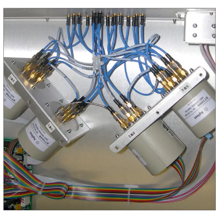
RF switching generally requires multiple routes and interconnects
A route across relay layers combines relays, cables, adapters and connectors. Each adds loss and can change with operation, temperature or handling. A recorded route and baseline let a team treat the path as part of the measurement chain and separate a change in the equipment from a change in the test system.
How does relay life limit an RF test path?
Relay life limits an RF test path because relays see different loads and different numbers of operations. A cycle count is the number of actuation cycles recorded for one relay, using the counting convention in its specification. A frequently selected route may exercise some relays on every test, while others move only during setup.
Mechanical endurance concerns operation of the mechanism under a specified condition. Electrical endurance concerns contacts making, carrying or breaking a defined load. The European Space Components Coordination (ESCC) latching relay specification separates low-level, resistive and inductive life procedures, and lists mechanical life separately in its test schedule. The U.S. Department of Defense relay specification also defines load-based life test conditions for its specified relay class. These are specification tests, not predictions of field life.
The actual relay documentation defines its permitted switching conditions and how operations are counted. VTEST’s RF switching hardware includes on-board relay odometers that track the cycle count of each relay. Per-relay records make uneven use visible and provide a more useful maintenance input than one matrix total.

Soft front-panels provide many useful data such as product life cycle and odometer for each path
How do you avoid hot switching in a test sequence?
Hot switching is avoided by removing or reducing RF power before a relay changes state, then restoring the source after the route is established. Hot switching means a contact changes state while RF power is applied; cold switching means the source is off or attenuated before the transition.
When contacts separate while current is flowing, an arc may form across the gap. Repeated arcing heats and erodes contact surfaces or transfers material, which can increase contact resistance and eventually impair switching.
Parallel steps may share a source or route, an error handler may redirect signals while the source remains enabled, or a reset may move relays before source state is confirmed. The source and relay commands need to be handled as one operation, including abort and recovery paths.
A simple sequence is:
Command the RF source off, or reduce to a level permitted by the selected relay specification.
Wait for the source off or reduced state to be confirmed.
Command the relay transition.
Verify the route or available relay state indication.
Restore the RF source only after the required path is established.
The wait and confirmation depend on the source and control interfaces. They should be explicit rather than assumed from command order. A delay alone is not enough if another branch can enable RF during the transition.
What makes an RF path repeatable?
An RF path is repeatable when its connections, relay route, cable geometry, temperature and reference plane are controlled between measurements. Repeatability often matters more than absolute loss: a stable offset can be characterised, while a route that changes between runs cannot be corrected with one fixed value.
A National Institute of Standards and Technology (NIST) study models changes across repeated vector network analyser (VNA) measurements of 1.85 mm coaxial offset shorts. The study is specific to that connector format and setup, not a universal acceptance limit. Its connector repeatability study illustrates why reconnecting belongs in the measurement procedure.
The National Physical Laboratory (NPL) describes assessing connector repeatability through repeated disconnect and reconnect measurements while other alignment conditions are held constant. Specify connector torque, adapter arrangement and cable routing for the actual setup. See the NPL guide to precision coaxial connectors.
Cable movement can alter phase and loss. Relay contacts and connectors also experience different histories when switched or reconnected often, while temperature can change electrical behaviour. Recording conditions, or correcting for known differences, keeps a baseline and a later check comparable.
The reference plane is the defined electrical point at which a measurement is calibrated or compared. Using the same connector or test port for each check keeps comparisons consistent.
How do you design the path to protect it?
Protect the path by turning each known risk into a design measure and a check that can be repeated. The test specification and the actual relay documentation determine the final limits.
Risk | Design measure | How to verify |
Relay wear | Count cycles per relay and set a review point from its documentation. | Compare per-relay counts with the recorded limit. |
Hot switching | Control source state and relay commands in normal, fault and recovery sequences. | Test each sequence with source state recorded. |
Unsafe combinations | Define an exclude list of relay combinations that must not close together. | Check configured routes against documented exclusions. |
Path drift | Store a baseline for each named route. | Compare path loss with the baseline and agreed limits. |
Connector variation | Specify torque, adapter arrangement and reconnect procedure. | Repeat the procedure and record conditions. |
Traceability | Keep stable path names, relay maps and change records. | Match the commanded route to its controlled record. |
A useful log holds each route and relay map, per-relay counts, verification results and references, connector changes, relay replacements, dates and configuration. These records help distinguish gradual drift from changes introduced by maintenance or a revised route.
What can these measures not do?
Path protection makes change easier to detect and manage, but it does not prove that every relay or measurement is healthy. Each measure has a limited scope.
An odometer counts operations, not contact condition. Two relays with the same count can behave differently because their routes, loads and environments differ. The count supports planning; it does not replace a path measurement.
Cold switching reduces electrical stress during a relay transition, but the mechanism still moves and the rest of the path remains exposed to connector variation, temperature and handling. A path check can show.
that a result changed, but it does not identify whether the cause is a relay, cable, connector, source or measurement setup.
An exclude list applies only to combinations defined and loaded correctly. It cannot anticipate an unlisted route or a configuration error. There is no universal relay life number across relay types, contact loads and switching modes; a count without the relevant specification is not a replacement rule.
Calibration and path verification answer different questions. Calibration establishes a measurement system’s relationship to a reference; verification checks a configured route against a baseline or acceptance condition.
Protection has a cost. Source control, verification, logging and route review add sequence time and engineering effort, and some installations may need extra hardware. The balance depends on the consequence of a wrong result and the available test time.
How should teams plan RF switching in automated test?
Start with the signals and power levels, then define routes and decide how each route will be counted, sequenced and verified. Record the choices before the test program depends on them.
1. List each RF path with its frequency range, source and receive power, direction and required repeatability.
2. Map shared relays and identify routes with frequent use or high consequence.
3. Check each relay’s documentation against expected signal levels and switching conditions.
4. Define cold switching sequences for normal, parallel, abort and recovery cases.
5. Set a relay review or replacement point from the relevant documentation and recorded use.
6. Define each path’s reference plane, baseline and verification interval.
7. Log relay counts, verification results, connector or cable changes and relay replacements.
8. Document torque and reconnect procedures, then review the first period of use to see whether checks capture real changes.
Teams reviewing an RF switching setup can discuss their requirements with VTEST.

Graphical Interconnect Wizards help planning of the RF routes and decision for the switching elements
FAQ: RF test path protection questions answered
Does cold switching remove all relay wear?
No. It changes the electrical condition during the transition, but the mechanism still operates and the rest of the path can still change. It is a control, not a wear-free guarantee.
Why does path repeatability matter more than absolute insertion loss?
A stable loss can be included in calibration or test limits. If the same route changes between runs, one fixed correction cannot describe every result.
How do you decide when to replace an RF relay?
Use the relay specification, its count and the path verification history together.
What should be logged for an RF path over its life?
Keep the named route and relay map, per-relay counts, verification results, source conditions, connector changes and relay replacements. Record the configuration needed to compare checks over time.
How often should an RF path be verified?
There is no single interval for every installation. Set it based on cycle rate, measurement margin, consequence of a wrong result and environment, then review it when these conditions change.
Sources
European Space Components Coordination, ESCC Generic Specification No. 3602: Relays, Electromagnetic, Latching, Issue 5.
U.S. Department of Defense, MIL-PRF-39016F, General Specification for Relays, Electromagnetic, Established Reliability, Hermetically Sealed, copy hosted by NASA.
National Institute of Standards and Technology, Stochastic Modeling of Coaxial-Connector Repeatability Errors.
National Physical Laboratory, Guidance on using Precision Coaxial Connectors in Measurement.